
Your Browsing History

Meet Your Seller

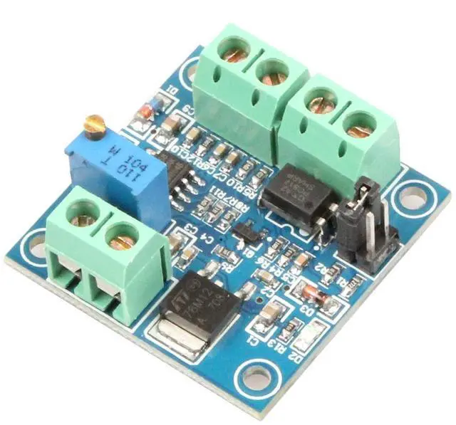
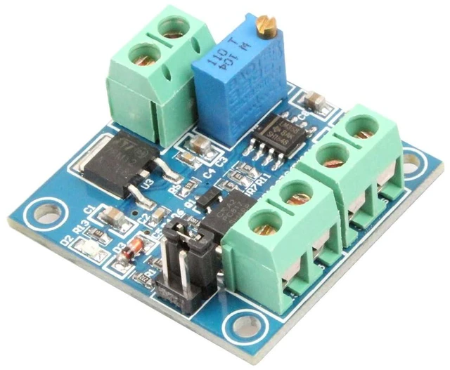

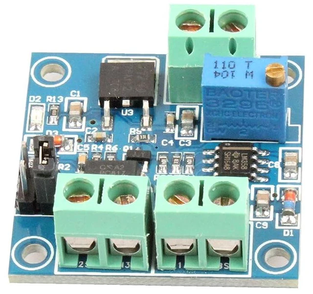
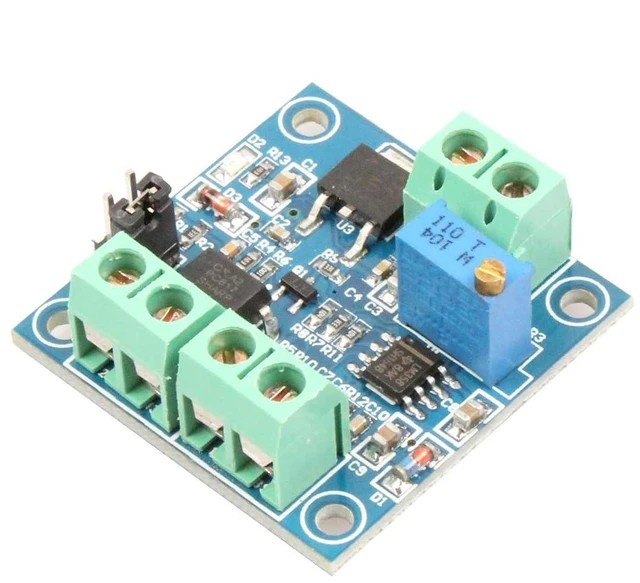


PWM to Voltage Module 0%-100% PWM to 0-10V Voltage Suitable for Signal Interface Switching for PLC or Other Industrial Control Boards
Limited time offer, ends 10/07 By Kepler Forge
- The PWM to voltage module converts PWM digital signals to 0 to 10V analog signals. It can be used to switch the signal interface of PLC or other industrial control board. Adjust the output voltage by adjusting the PWM duty cycle. The module is small in size and easy to apply in different places.; Using MCU embedded technology. Easy to operate, can be fine-tuned by potentiometer. Select the PWM signal input level range by short circuit. The module is small, easy to carry and easy to use.; Module working voltage: DC 12V-30V; (current greater than 100mA)PWM signal receiving frequency range: 1KHZ-3KHZ;; When power on for the first time, it is best to do a calibration and debugging: find a signal with a 50% duty cycle and connect it to PWM and GND. Jumper caps set the corresponding voltage range. When the frequency is 1KHZ-3KHZ, use a multimeter to measure the two ports of VOUT and GND. At this time, the meter displays about 5V. Adjust the potentiometer on the board so that the multimeter displays 5.00v.
+
+
Overview
Specs
Reviews
NOYITO PWM to Voltage Module User
Manual https: //1drv. ms/b/c/4a0865b22350d05c/IQBc0FAjsmUIIIBK8AAAAAAAARBO5STfKsInjaxlEoFeNiM? e=JAbHuc
Parameters Module working voltage: DC 12V-30V; (current greater than 100mA)
PWM signal receiving frequency range: 1KHZ-3KHZ;
PWM signal input level range: The peak-to-peak value is 4.5V to 10V, and the jumper cap is inserted at 5V. This type of level signal is mainly for the conventional industrial control card, 5V CPU interface; The peak-to-peak value is 12 to 24V, and the jumper cap is inserted at 24V. This type of level signal is mainly for the conventional PLC interface.
Conversion range: 0%-100% PWM conversion to 0-10V voltage
Allowable error: 5%.
Wiring instructions:
VCC: Working power supply 12V-30V.
GND: Working power ground.
PWM: Input the positive end of the PWM signal.
GND: Input signal negative terminal.
VOUT: Output voltage 0-10V.
GND: Output voltage ground.
Instructions: After power-on, when there is no input signal, the output is 0V. For the first power-on, it is best to do a calibration debug: find a 50% duty cycle signal to the PWM, GND, Jumper caps set the corresponding voltage range.. The frequency is 1KHZ-3KHZ. Use a multimeter to measure the two ports VOUT and GND. At this time, the meter is displayed at about 5V. Adjust the potentiometer on the board so that the multimeter is displayed at 5.00 v. This will calibrate your pulse signal and this module. the corresponding parameters. When the frequency changes, the corresponding parameters may be offset and need to be recalibrated. The output voltage can be adjusted by adjusting the duty cycle. Accuracy can be controlled by adjusting the potentiometer.
Package Included: 1pcsPWM to Voltage Module
Manual https: //1drv. ms/b/c/4a0865b22350d05c/IQBc0FAjsmUIIIBK8AAAAAAAARBO5STfKsInjaxlEoFeNiM? e=JAbHuc
Parameters Module working voltage: DC 12V-30V; (current greater than 100mA)
PWM signal receiving frequency range: 1KHZ-3KHZ;
PWM signal input level range: The peak-to-peak value is 4.5V to 10V, and the jumper cap is inserted at 5V. This type of level signal is mainly for the conventional industrial control card, 5V CPU interface; The peak-to-peak value is 12 to 24V, and the jumper cap is inserted at 24V. This type of level signal is mainly for the conventional PLC interface.
Conversion range: 0%-100% PWM conversion to 0-10V voltage
Allowable error: 5%.
Wiring instructions:
VCC: Working power supply 12V-30V.
GND: Working power ground.
PWM: Input the positive end of the PWM signal.
GND: Input signal negative terminal.
VOUT: Output voltage 0-10V.
GND: Output voltage ground.
Instructions: After power-on, when there is no input signal, the output is 0V. For the first power-on, it is best to do a calibration debug: find a 50% duty cycle signal to the PWM, GND, Jumper caps set the corresponding voltage range.. The frequency is 1KHZ-3KHZ. Use a multimeter to measure the two ports VOUT and GND. At this time, the meter is displayed at about 5V. Adjust the potentiometer on the board so that the multimeter is displayed at 5.00 v. This will calibrate your pulse signal and this module. the corresponding parameters. When the frequency changes, the corresponding parameters may be offset and need to be recalibrated. The output voltage can be adjusted by adjusting the duty cycle. Accuracy can be controlled by adjusting the potentiometer.
Package Included: 1pcsPWM to Voltage Module
Warranty & Returns
Warranty, Returns, And Additional Information
Warranty
- Please contact the Seller directly for warranty information. Warranty information may also be found on the Manufacturer's website.
- CONTACT
Return Policies
- Return for refund within: 30 days
- Return for replacement within: 90 days
- This item is covered by Kepler Forge Return Policy
Manufacturer Contact Info
- For a directory of all our manufacturers, please click below.
- Manufacturers Directory
LOADING...