



Meet Your Seller
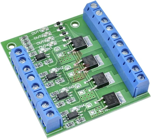
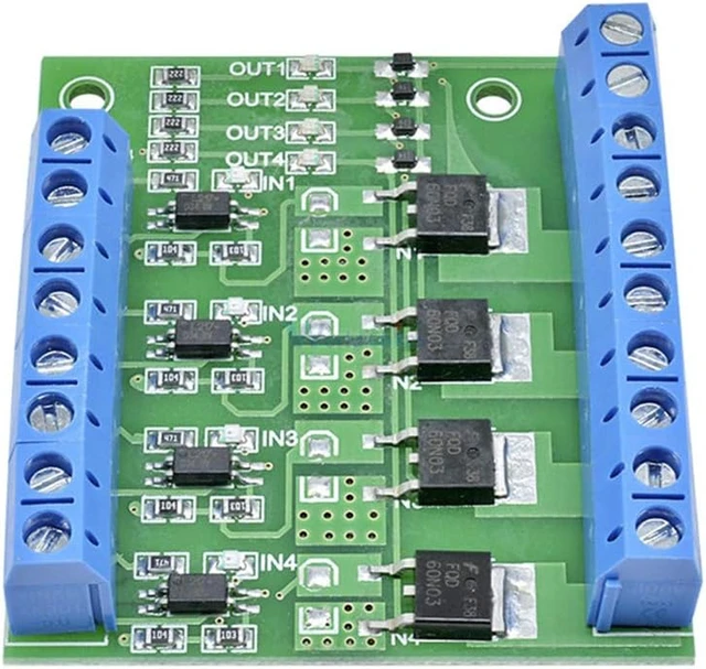


2 pack MOSFET Trigger Switch 4 Channel Drive Module 400W DC 3.7-27V 10A, Large Power, PWM Adjustment, Electronic Switch Control Board
- Operating Voltage: DC 3V - 27V; The trigger source: digital high-low (DC3V - 20V); continuous current: 10A; power: 400W.
- High Reliability, High Availability: The drive module using high quality ultra-small optocoupler, with strong anti-interference ability, and stable performance, is complete isolation of input signal and output.
- Supporting Multiple Signal Source Triggers: Can be connected microcontroller IO port, PLC interfaces, DC power, etc.
- PERFECT SUPPORT PWM: You can access the PWM signal, the signal frequency 0--20KHZ perfect support.
- WIDELY APPLICATIONS: You can control the output of power equipment, motors, light bulbs, LED lights, DC motors, micro-pumps, solenoid valves, etc., can input PWM, control motor speed, lamp brightness and so on.
+
+
Overview
Specs
Reviews
The board is of high power MOS trigger switch driver module and control board with field-effect tube to adjust the electronic switch. Besides it works at 10A,400W under common temperature which satisfies most devices usage and realizes the control of great power devices in a relaxed way.
Technical Specifications:
Operating Voltage: DC 3V - 27V
The trigger source: digital high-low (DC3V - 20V), can be connected microcontroller IO port, PLC interfaces, DC power, you can access the PWM signal, the signal frequency 0--20KHZ perfect support
Output capacity: DC 3.7V - 27V, at room temperature, continuous current 15A, power 400W
Applications: You can control the output of power equipment, motors, light bulbs, LED lights, DC motors, micro-pumps, solenoid valves, etc., can input PWM, control motor speed, lamp brightness and so on
PWM frequency: 0-200Hz
With input signal indicator
With output indicator
Operating temperature: -40-85
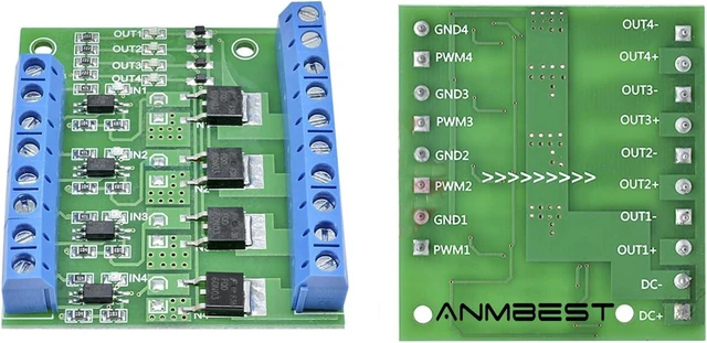
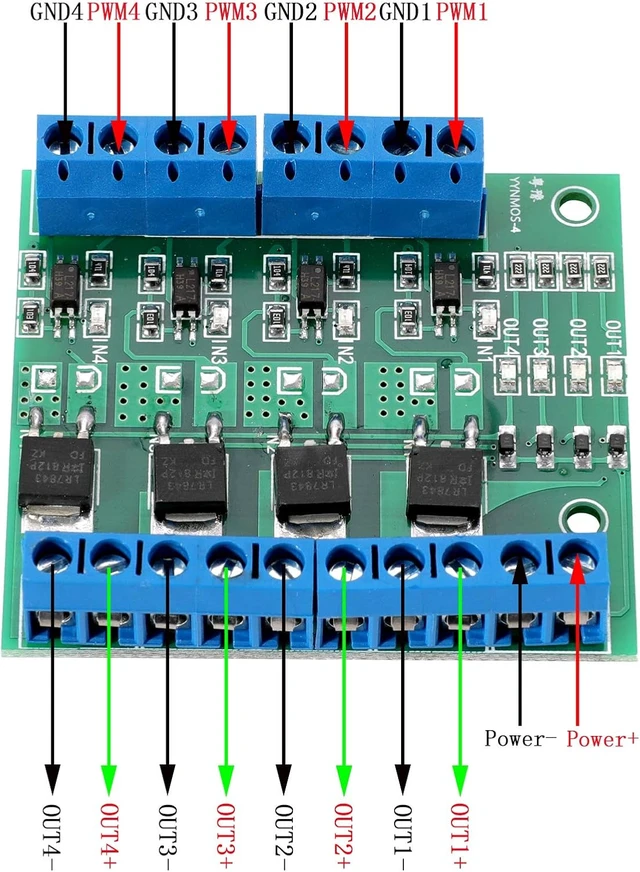
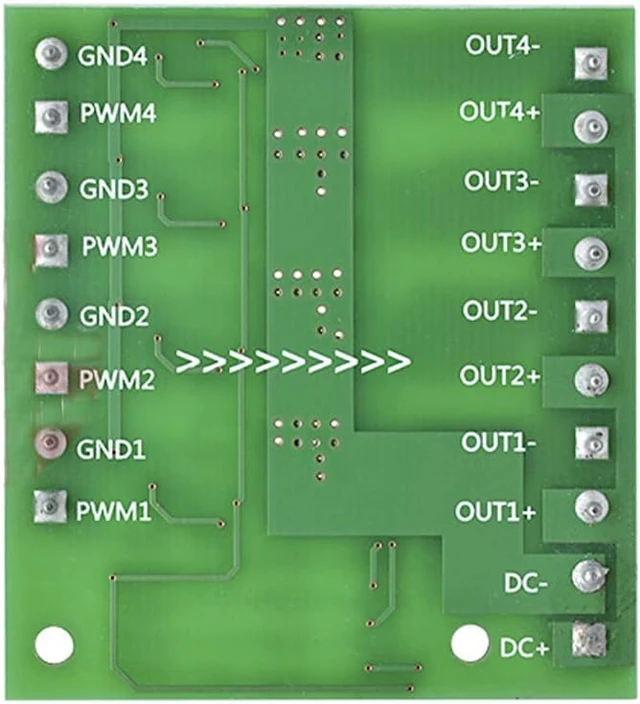
Module interface:
DC+: The positive pole of the device's DC power supply
DC-: The negative pole of the device's DC power supply
PWM: signal input terminal (connected to MCU IO port, PLC interface, DC power supply, etc.)
GND: signal negative terminal
OUT+: Positive output terminal (connect to the positive terminal of the device)
OUT-: The negative pole of the output terminal (connect to the negative pole of the device)
Package includes:
1 X 4 Channel MOS FET Trigger Switch Drive Module
Warranty & Returns
Warranty, Returns, And Additional Information
Warranty
- Please contact the Seller directly for warranty information. Warranty information may also be found on the Manufacturer's website.
- CONTACT
Return Policies
- Return for refund within: 30 days
- Return for replacement within: 90 days
- This item is covered by Pinpoint One Return Policy
Manufacturer Contact Info
- For a directory of all our manufacturers, please click below.
- Manufacturers Directory
LOADING...