
Your Browsing History

Meet Your Seller

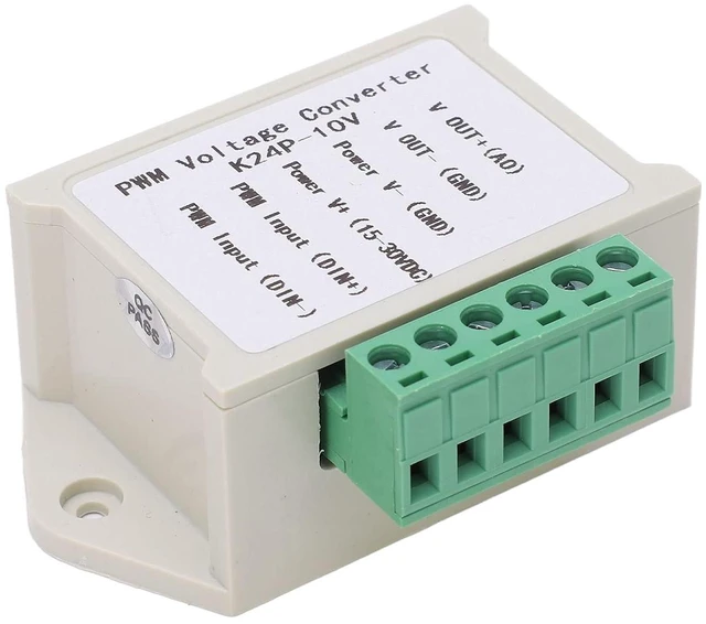
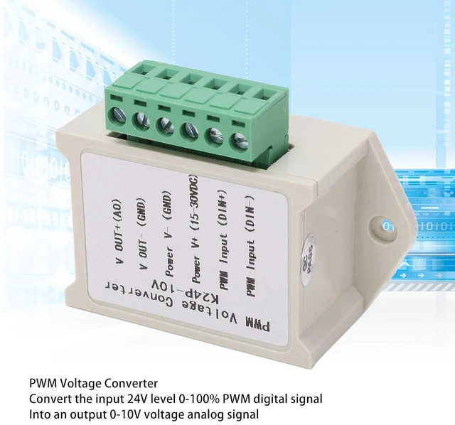
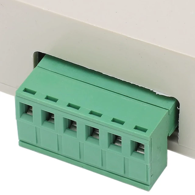
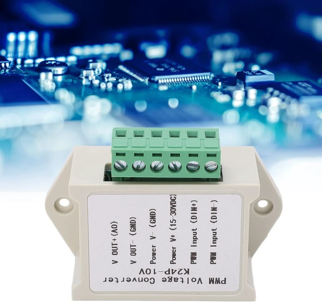


PWM to Voltage Module 0100% to Digital 010V PWM Voltage Converter Analog to Digital Conversion Module for Interface Switching
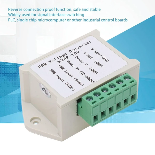
- SIGNAL CONVERSION: Convert the input 24V level 0100% PWM digital signal into an output 010V voltage analog signal; STABLE CONNECTION: The power supply has reverse connection proof function, safe and stable, you can use with confidence; SCOPE OF APPLICATION: Widely used for signal interface switching of PLC, single chip microcomputer or other industrial control boards; SCRATCH ABS: Adopt excellent ABS material, possess impact resistance, scratch resistance, environmentally friendly; STABLE AND DURABLE: PWM voltage converter come with stable structure, excellent performance and long service life
+
+
Overview
Specs
Reviews
Product description PWM to Voltage Module 0? 100% Signal to Digital 0-10V PWM Voltage Converter Analog to Digital Conversion Module for Signal Interface Switching SCOPE OF APPLICATION: Widely used for signal interface switching of PLC, single chip microcomputer or other industrial control boards
SCRATCH ABS: Adopt excellent ABS material, possess impact, scratch, STABLE
CONNECTION: The power supply has reverse connection proof function, safe and stable, you can use with confidence How to
Use: After power on, when there is no input signal, the output is 0V, and there is input before output When powering on for the first time, you can do a calibration and debugging: find a signal with a 50% duty cycle and connect it to DIN, DIN+, and the amplitude corresponds to 24V. When the frequency is 1KHZ3KHZ, use a multimeter to measure the two ports of AO and GND. At this time, the meter displays about 5.4V. Adjust the potentiometer on the board to make the multimeter display 5.40 v. In this way, your pulse signal is calibrated with this module correspondence. The resolution of this module is 0.1V. The output current capability is 10MA. If the relationship between the percentage of the duty cycle and the voltage is opposite, you can check (or cross check) the pin for setting the PWM output in the for software and click the check box of the corresponding pin of STEP LOW and ACTIVE.
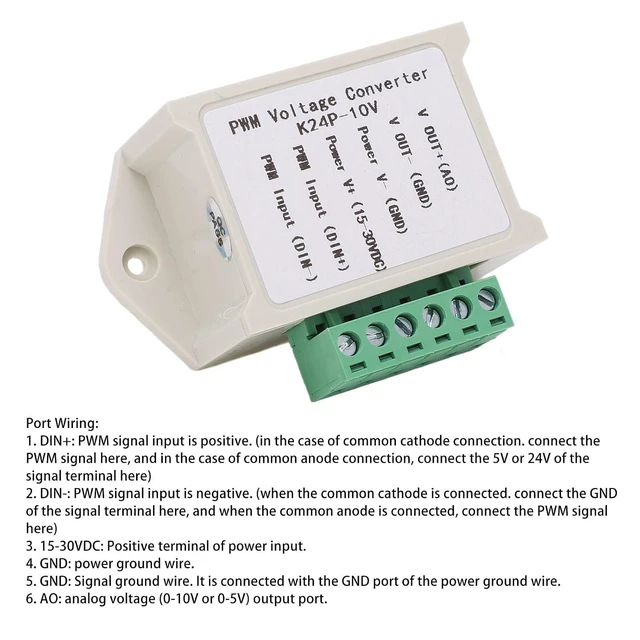
Port Wiring: 1.
DIN+: PWM signal input is positive. (in the case of common cathode connection. connect the PWM signal here, and in the case of common anode connection, connect the 5V or 24V of the signal terminal here) 2.
DIN: PWM signal input is negative. (when the common cathode is connected. connect the GND of the signal terminal here, and when the common anode is connected, connect the PWM signal here) 3.
1530VDC: Positive terminal of power input. 4.
GND: power ground wire. 5.
GND: Signal ground wire. It is connected with the GND port of the power ground wire. 6.
AO: analog voltage (010V or 05V) output port.
Specification: Item
Type: PWM
Voltage Converter Material: ABS
Input: 0-100% PWM signal of 24V
Output: 0-10V
Conversion Method: Analog to digital
Package List: 1 x PWM
Voltage Converter Note: Match the appropriate model before use.
SCRATCH ABS: Adopt excellent ABS material, possess impact, scratch, STABLE
CONNECTION: The power supply has reverse connection proof function, safe and stable, you can use with confidence How to
Use: After power on, when there is no input signal, the output is 0V, and there is input before output When powering on for the first time, you can do a calibration and debugging: find a signal with a 50% duty cycle and connect it to DIN, DIN+, and the amplitude corresponds to 24V. When the frequency is 1KHZ3KHZ, use a multimeter to measure the two ports of AO and GND. At this time, the meter displays about 5.4V. Adjust the potentiometer on the board to make the multimeter display 5.40 v. In this way, your pulse signal is calibrated with this module correspondence. The resolution of this module is 0.1V. The output current capability is 10MA. If the relationship between the percentage of the duty cycle and the voltage is opposite, you can check (or cross check) the pin for setting the PWM output in the for software and click the check box of the corresponding pin of STEP LOW and ACTIVE.
Port Wiring: 1.
DIN+: PWM signal input is positive. (in the case of common cathode connection. connect the PWM signal here, and in the case of common anode connection, connect the 5V or 24V of the signal terminal here) 2.
DIN: PWM signal input is negative. (when the common cathode is connected. connect the GND of the signal terminal here, and when the common anode is connected, connect the PWM signal here) 3.
1530VDC: Positive terminal of power input. 4.
GND: power ground wire. 5.
GND: Signal ground wire. It is connected with the GND port of the power ground wire. 6.
AO: analog voltage (010V or 05V) output port.
Specification: Item
Type: PWM
Voltage Converter Material: ABS
Input: 0-100% PWM signal of 24V
Output: 0-10V
Conversion Method: Analog to digital
Package List: 1 x PWM
Voltage Converter Note: Match the appropriate model before use.
Warranty & Returns
Warranty, Returns, And Additional Information
Warranty
- Please contact the Seller directly for warranty information. Warranty information may also be found on the Manufacturer's website.
- CONTACT
Return Policies
- Return for refund within: 30 days
- Return for replacement within: 90 days
- This item is covered by Kepler Forge Return Policy
Manufacturer Contact Info
- For a directory of all our manufacturers, please click below.
- Manufacturers Directory
LOADING...